1. Home
  2. »
  3. High-Precision Automatic Calibration Unit

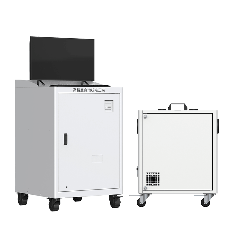
High-Precision Automatic Calibration Unit

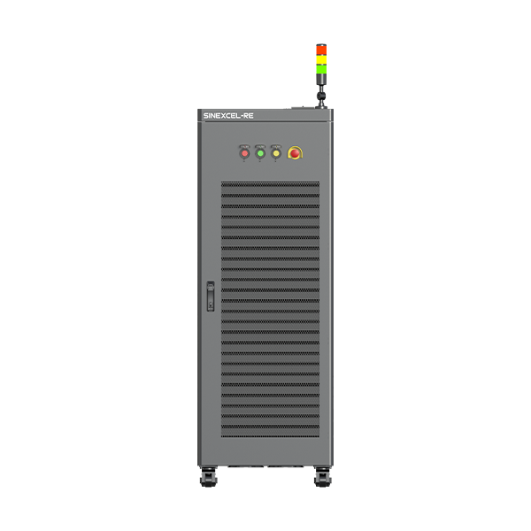
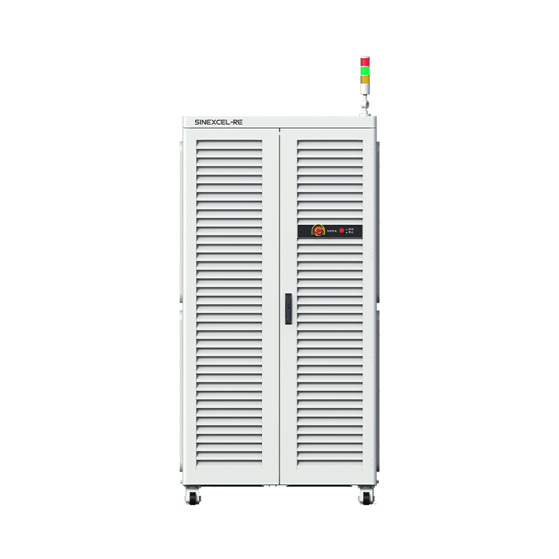
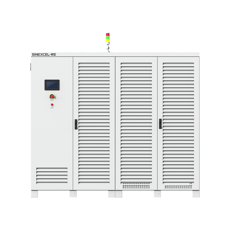
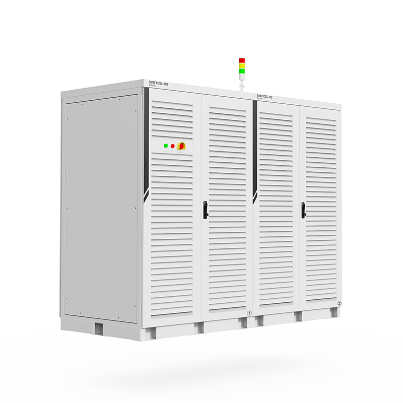
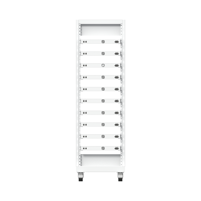
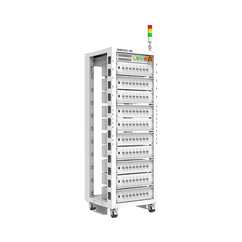
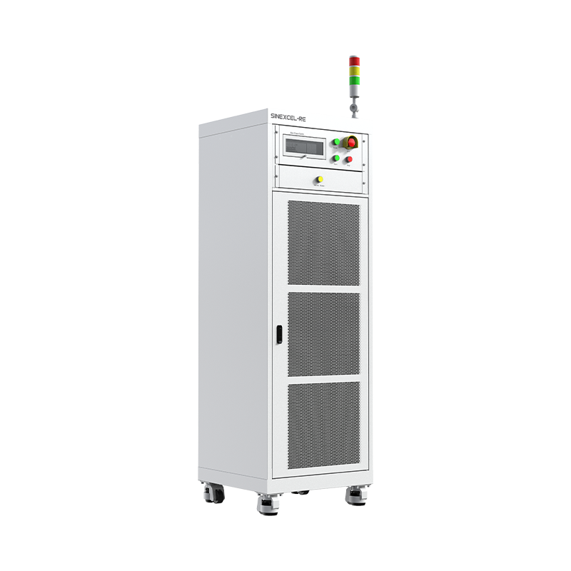
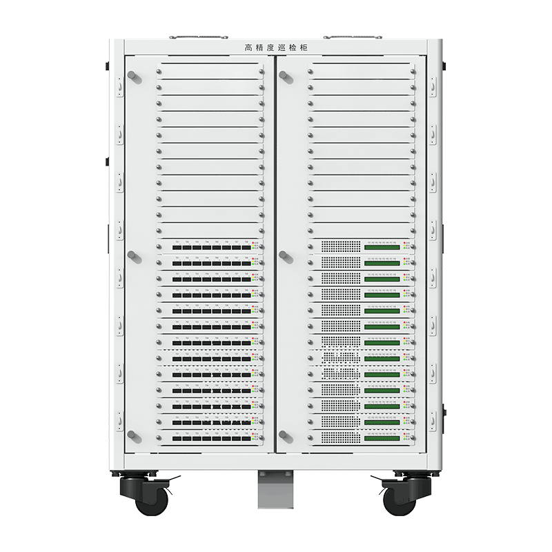
The High-Precision Automatic Calibration Unit enables one-click, multi-channel automatic calibration of voltage and current for the battery charge-discharge test system with high efficiency. It generates customized calibration reports to archive calibration data and ensure traceability.

Detailed Introduction

The High-Precision Automatic Calibration Unit is designed for fast and accurate calibration of battery charge-discharge testing equipment. It uses high-precision measurement instrumentation to automatically calibrate voltage and current channels across a wide operating range, helping maintain measurement accuracy and consistency throughout battery testing operations.

The system supports voltage calibration from 0V to 2000V and current calibration from 0A to 1500A. It can automatically match the calibration range of the connected equipment and complete calibration of each channel in ≤2 minutes, significantly reducing manual calibration time.

System Features

Utilizes ultra-high precision instrumentation to ensure calibration accuracy
Supports current calibration from OA to 1500A, with automatic matching of equipment ranges
Features a high degree of automation, enabling one-click automatic calibration with a cycle time of s2 mins/CH
Allows for customized calibration plans, automatically generates reports, and ensures full calibration traceability

Key System Parameters

Parameters

Calibration Range

Voltage: OV to 2000V
Current: OA to 1500A

Calibration Time per Channel

≤2 mins /CH

Digital Multimeter

6.5 digital DMM from Top-tier International Brand

Calibration Accuracy

0.01% F.S (Hall Sensor or Current Shunt)

Functions

Automatic Calibration

One-click automatic calibration with report generation.

Automatic Verification

One-click automatic verification with report generation

Manual Calibration

Select the calibration point (Voltage, Current) manually

Manual Verification

Select the verification point (Voltage, Current) manually

Customized Report

Customized Calibration Configuration with Automatic Deviation Analysis

FAQ

Battery Overvoltage
Battery voltage exceeds the upper voltage limit, confirmation time 0.2s
  1. Use a multimeter to measure the actual battery voltage and compare it with the voltage displayed on the BTS to check if the sample values are consistent.
  2. If the sample value and the actual value are not equal, confirm whether the issue is with the DC board or the wiring by swapping the sampling lines with adjacent channels. If the wiring is faulty, check for incorrect, loose, or poor connections in the voltage sampling lines.
  3. If the sample value and the actual value are equal, check if the upper computer step settings are reasonable and determine if the battery overvoltage occurs as soon as the step runs or at a specific point during the step.
  4. Check the corresponding battery for any obvious swelling, damage, or other abnormalities. If there are issues, take necessary safety measures.
  5. If the battery and voltage sampling lines are normal, confirm that the DC board is faulty and replace it.
Battery Undervoltage
Battery voltage is lower than the lower voltage limit, confirmation time 0.2s
  1. Use a multimeter to measure the actual battery voltage and compare it with the voltage displayed on the BTS to check if the sample values are consistent.
  2. If the sample value and the actual value are not equal, confirm whether the issue is with the DC board or the wiring by swapping the sampling lines with adjacent channels. If the wiring is faulty, check for incorrect, loose, or poor connections in the voltage sampling lines.
  3. If the sample value and the actual value are equal, check if the upper computer step settings are reasonable and determine if the battery undervoltage occurs as soon as the step runs or at a specific point during the step.
  4. Check the corresponding battery for any obvious swelling, damage, or other abnormalities. If there are issues, take necessary safety measures.
  5. If the battery and voltage sampling lines are normal, confirm that the DC board is faulty and replace it.
Communication Failure
Module 6S does not receive data from the upper computer, switches to fault state. The fault is automatically cleared when the module receives data from the upper computer.
  1. Check if the module and the middle computer are in a normal powered-on state.
  2. Check if the CAN connection between the module and the middle computer is normal.
  3. Check if the CANA dip switch is set correctly.
  4. Measure the matching resistance between CAN H and CAN L on the CANA bus. It should be 60±5 ohms. If not, adjust the matching resistance on the signal adapter board. If the bus voltage is normal, check the BTS fault records to identify which sub-channel triggered the fault. Use debugging software tools to check if the bus voltage displayed for that channel is normal. If abnormal, it can be determined that the DC board's bus sampling is faulty, and the board should be replaced.
  5. If all the above points are normal, connect a CAN box and use the captured messages to determine whether the issue lies with the middle computer or the lower computer.

Our Products

Our range of battery test equipment includes various specialized test systems such as the Milliampere-level Test System, IT Battery Test System, and EV Battery Test System, among others

Let’S Build The Future With Innovation.

Please Provide The Following Details To Help Our Sales Representativesbetter Understand Your Needs And Get In Touch With You As Soon

Scroll to Top