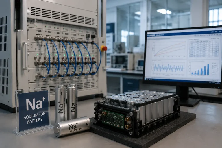
The last 10 years have seen significant increases in the complexity of battery testing. The tools that engineers use must keep up with what they are expected to measure, as new cell chemistries, tighter performance specifications and more demanding cycle life targets are all pushing the capabilities of the tools. Bipolar power supplies are one technology quietly changing the face of this space, and gaining an understanding of what they are, how they differ from the traditional power supply, and why they are so important is growing increasingly paramount for any serious battery test lab.
What Is a Bipolar Power Supply?
A bipolar power supply is constructed around just one four quadrant architecture of a DC/DC converter. Bipolar differs from a traditional bidirectional supply in that it utilizes the same hardware for charging or discharging. The current always flows in the same direction, transitioning from charge to discharge and back again and never breaking in the transition zone.
This implies that voltage and current is capable of being continuously controlled both in magnitude and direction in one and the same topology. The supply must not stop or switch loops or wait for the one circuit to disengage before the other one is engaged. It’s a completely new approach to managing bi-directional power flow and has significant effects on the quality of the measurements being made.
Why Conventional Bidirectional Power Supplies Fall Short

To appreciate what bipolar architecture offers, it helps to understand what came before it and where that older approach breaks down.
The bidirectional power supply was itself an improvement when it arrived. Before it, battery test labs needed separate instruments for charging and discharging — a dedicated charger and a separate electronic load. The bidirectional supply combined both into a single unit, which simplified bench setups and reduced hardware overhead. For years, this was the standard configuration in battery test equipment.
However, the design carries a structural limitation that becomes increasingly problematic as test demands grow more exacting.
A conventional bidirectional supply contains two distinct circuit loops. When the system needs to switch from charging to discharging — or vice versa — it must shut down the active loop, hold for a brief dead time, and then activate the other. During that interval, current drops to zero. The pause is short, often just milliseconds, but it is real.
In everyday power conversion applications, a momentary current interruption of this kind is largely inconsequential. In precision battery testing, it is not. The zero-crossing gap introduces a distortion into the voltage waveform at exactly the moment a transition occurs. Voltage can bounce or spike at the crossing point. The resulting signal is not a clean reflection of the battery’s behavior — it is the battery’s behavior plus an artifact introduced by the power supply itself.
For testing engineers whose measurements depend on catching small voltage deltas with accuracy, this error is not a minor inconvenience. It directly undermines the validity of results across multiple test types, including DCIR, HPPC, and dynamic drive cycle simulation.
Why This Matters in Battery Testing
The stakes of measurement accuracy in battery testing are higher than they might appear from the outside. Labs performing cell development, aging analysis, state-of-health modeling, and production quality control are all making decisions based on the data their equipment produces. When that data carries embedded error, those decisions are built on a flawed foundation.
Consider the practical consequences in a development lab working on next-generation lithium-ion or sodium-ion cells. Engineers running aging analysis depend on DCIR measurements taken at regular intervals throughout the cell’s life to track how internal resistance evolves. If each measurement carries a consistent bias introduced by zero-crossing artifacts, the degradation curves they produce will be systematically off. They may conclude a cell is aging faster or slower than it actually is, or they may attribute performance differences between cells to chemistry when the real source of variation is the test equipment.
In an EV battery R&D environment, the consequences extend further. Pack-level validation requires drive cycle simulation — running a battery through profiles that replicate real-world driving conditions including regenerative braking, acceleration, and sustained load. These profiles demand frequent, rapid polarity changes in the current waveform. A power supply that cannot execute those transitions cleanly is not simulating the drive cycle the engineer specified. It is simulating an approximation of it, with the fidelity of that approximation determined by how quickly the zero-crossing dead time distorts the intended profile.
Bad data in this context is expensive in multiple ways. It costs time in repeated tests. It may cost product development cycles if engineers optimize their designs around measurement artifacts that do not represent real battery behavior. And it adds uncertainty to results that lab managers and development teams need to trust.
Seamless switching, the defining characteristic of bipolar architecture, addresses this problem at its source. Because the bipolar supply uses a single converter loop that operates continuously in both quadrants, there is no mode transition and no dead time. Current passes through zero smoothly and continuously. The voltage signal at the crossing point reflects the battery’s actual response, not a mixing of battery response and switching artifact.
Real Testing Scenarios Where Bipolar Architecture Makes a Difference

DCIR Testing
Direct Current Internal Resistance is one of the most widely used indicators of battery health. The measurement protocol is straightforward: apply a step current pulse, observe the resulting voltage change, and compute resistance using Ohm’s law. The simplicity of the calculation is somewhat deceptive, because the accuracy of the result depends entirely on the quality of the voltage delta measurement.
With a conventional bidirectional supply, applying a step current that crosses zero — moving from a discharge pulse to a charge pulse or vice versa — introduces a voltage spike or bounce at the crossing point. The delta V measured by the data acquisition system captures this artifact as part of the signal. The computed resistance is therefore not the true internal resistance of the cell. It may be lower than the actual value, or it may fluctuate inconsistently between test runs on the same cell, making it difficult to distinguish genuine aging trends from test noise.
In a bipolar supply, the step current is applied continuously and the transition is uninterrupted. The voltage response reflects only the battery’s behavior. The DCIR value calculated from that measurement is accurate, repeatable, and reliable enough to base cell selection, aging analysis, and state-of-health modeling on.
Cyclic Voltammetry
Cyclic voltammetry is an electrochemical test method used in battery research to understand reaction kinetics and identify degradation mechanisms. The test sweeps the cell voltage back and forth across a defined range while recording the current response. By its nature, the current crosses zero multiple times during each sweep cycle.
In a conventional bidirectional supply, each zero crossing is accompanied by a switching action — the supply momentarily pauses as it transitions between its two circuit loops. This pause introduces jitter into the current curve at the crossing point. The artifact may be small in absolute terms, but in cyclic voltammetry, where researchers are looking for subtle features in the current response to identify specific electrochemical events, even small artifacts can obscure the signals they are trying to measure.
A bipolar supply passes through zero continuously, with no switching action and no current interruption. The cyclic voltammetry curve is a faithful representation of the cell’s electrochemical dynamics, not a mixture of those dynamics and power supply behavior.
Dynamic Drive Cycle Simulation
Simulating real-world driving conditions is a critical part of EV battery development and validation. Standard drive cycles such as NEDC and WLTP, as well as custom profiles for specific applications, require the power supply to change current direction frequently and rapidly — sometimes within milliseconds. Regenerative braking simulation, for example, involves a transition from discharging to charging and back to discharging in the span of a few hundred milliseconds or less.
A conventional bidirectional supply cannot execute these transitions without a delay. Each polarity reversal requires the supply to complete its dead time sequence, meaning the current profile fed to the battery deviates from the intended profile at every transition point. The more transitions the profile contains, the greater the cumulative deviation from the target.
Bipolar supplies can follow dynamic load changes with short response times because there are no switching loops to manage and no dead time to observe. The current profile delivered to the battery tracks the intended waveform closely. Drive cycle simulations run on a bipolar platform represent the actual operating conditions the engineer designed for, making the test results meaningful for real-world performance prediction.
The Next Frontier: Solid-State Batteries and What They Demand
Battery technology is continually progressing. The development of solid-state batteries, based on sulfide, oxide or polymer electrolytes, is moving from laboratory research to early commercialization. They are a major advancement in density of energy and safety, and, at the same time, they bring new test equipment challenges.
There are characteristics of solid state cells that are different than traditional liquid electrolyte batteries, and these differences have an impact on testing. They tend to have higher internal resistance values and are sensitive to the conditions under which they are measured. The higher the resistance value of a solid-state cell and the more complex the physical phenomenon, the tighter the tolerances for voltage measurement that are needed for DCIR testing. With solid-state chemistries, small errors that may be acceptable in lithium-ion testing are not acceptable.
At the same time, solid-state cells require tighter control over voltage excursions during testing — the tolerance windows for charge and discharge are narrower, and the consequences of exceeding them during a test can be more severe than with conventional cells.
The gap between conventional bidirectional power supplies and bipolar designs becomes wider in this context. For labs beginning to work with solid-state cell formats — or preparing to scale testing as solid-state chemistries move toward production — a bipolar architecture is not merely a quality-of-life upgrade. It is a prerequisite for generating measurement data that is accurate enough to be useful.
Building a Testing Platform Around Bipolar Architecture
Understanding the technical case for bipolar power supplies leads naturally to questions about implementation: what does a lab actually need from a bipolar-based battery test platform, and how should testing engineers evaluate available options?
The core requirements are well understood among experienced lab managers. Measurement accuracy, response time, software integration, and scalability all matter. But the deeper question is whether the power architecture underlying a test system can genuinely support the test protocols in use today and those likely to be needed over the next several years. A lab that begins with a bipolar foundation avoids the retrofitting challenges that come with trying to adapt conventional bidirectional equipment to test cases it was not designed for.
Power Module Specifications That Matter
A battery test system is only as capable as its power module. The module converts grid power into the precisely controlled voltage and current the cell, module, or pack under test needs to see. It determines measurement accuracy, response speed, and the system’s ability to handle edge cases safely.
Modern bipolar test platforms built on Silicon Carbide (SiC) MOSFET technology offer meaningful advantages over older silicon-based designs. SiC enables higher switching speeds with lower switching losses, which translates to faster dynamic response and better measurement accuracy across the operating range. Key specifications to evaluate in a battery testing power module include:
- Voltage and current accuracy — 0.02% full-scale is achievable with SiC-based designs and is worth seeking in equipment intended for precision R&D or production quality control.
- Data acquisition rate — synchronized hardware sampling at 1ms intervals supports accurate capture of fast transients during DCIR pulses and dynamic simulation.
- Regenerative efficiency — systems that return energy to the grid rather than dissipating it as heat can recover a significant portion of the power consumed during charge-discharge cycling, reducing operating costs in high-throughput labs.
- Multi-range switching — automatic switching across current ranges without interrupting the measurement avoids the data gaps that occur with manual range changes.
- Dynamic response time — a 20ms response to step changes in load supports accurate drive cycle simulation.
Scalability Across the Development Workflow
Battery testing requirements differ substantially at different stages of the development and production workflow. Early-stage materials and cell research demands milliampere-level resolution for small cells in controlled environments. Cell development and characterization scales up to the ampere range with requirements for multi-protocol flexibility. Module and pack-level testing requires wider voltage ranges, thermal management integration, and often multi-channel coordination.
A platform designed for scalability allows a lab to work within a consistent software environment and data management framework across all of these stages. Engineers testing a sodium-ion pouch cell in development and then validating a complete 800V pack for a production vehicle program can work from the same platform without switching data formats or rebuilding test scripts.
This kind of coherence across the testing workflow also simplifies the integration of ancillary systems — thermal chambers, water coolers, battery management system interfaces — that are standard in comprehensive battery lab environments. Protocol support across CAN, CANFD, and RS485 covers the range of communication standards in use across modern battery development and manufacturing.
Conclusion
The shift from conventional bidirectional to bipolar power supply architecture in battery testing is not driven by marketing preference or incremental feature competition. It reflects a genuine technical requirement that has become more acute as battery chemistries have grown more complex and test protocols more demanding.
The zero-crossing problem inherent in conventional bidirectional designs was manageable when testing tolerances were wider and the cells under test were better understood. As internal resistance measurements need to be accurate enough to track aging in novel chemistries, as drive cycle profiles grow more dynamic, and as solid-state cells push the boundaries of what test equipment is asked to measure, the interruption introduced by a switching dead time carries real consequences for data quality.
Seamless switching — continuous, uninterrupted current flow through zero in a single four-quadrant converter — removes that source of error. It gives testing engineers clean signals that represent battery behavior rather than a mixture of battery behavior and instrument artifacts. It makes DCIR, cyclic voltammetry, HPPC, and dynamic simulation results more reliable, and it does so across all of these test types within a single platform without requiring engineers to make compromises between test fidelity and instrument capability.
For labs at the forefront of battery development — working on solid-state chemistries, validating next-generation EV packs, or running high-throughput production QC — the move to bipolar architecture is increasingly less of a choice and more of a necessity. The precision that current and future battery technologies require simply exceeds what conventional bidirectional equipment can reliably deliver.
The labs investing in bipolar-based test platforms today are positioning themselves to work with the battery technologies that will define the next decade of energy storage without having to retrofit their measurement infrastructure when those chemistries arrive.
FAQ
What is a bipolar power supply?
A bipolar power supply is a power electronics system built on a single four-quadrant DC/DC converter. It can supply both positive and negative voltage and current continuously within the same hardware, without requiring separate circuit loops for each direction. This allows it to transition seamlessly between charging and discharging a battery without any interruption in current flow.
What is seamless switching?
Seamless switching refers to the ability of a bipolar power supply to change current direction — from positive to negative or back — without pausing, switching circuit loops, or introducing a dead time at the zero-crossing point. The current waveform passes smoothly through zero, and the voltage signal remains a continuous, uninterrupted reflection of the battery’s actual response.
Why does zero-crossing matter in battery testing?
When a conventional bidirectional supply transitions between charging and discharging, it must briefly stop current flow at zero as it switches between its two internal circuit loops. This brief interruption distorts the voltage waveform at the transition point, introducing artifacts into measurements like DCIR and cyclic voltammetry. In precision battery testing, these artifacts can introduce systematic error into results, leading to inaccurate resistance measurements, distorted electrochemical curves, and drive cycle profiles that deviate from the intended waveform.
What is a four-quadrant power supply?
A four-quadrant power supply can operate in all four combinations of positive/negative voltage and positive/negative current. This gives it the ability to both source and sink energy in either polarity continuously — a capability that is essential for seamless bidirectional battery testing. Conventional bidirectional supplies approximate this behavior using two separate one- or two-quadrant circuits, which is why they require a switching interval when changing direction.
How does bipolar architecture improve DCIR testing?
DCIR (Direct Current Internal Resistance) is measured by applying a step current to a cell and observing the voltage change. The accuracy of the result depends on the cleanliness of the voltage delta at the transition. With a conventional bidirectional supply, the zero-crossing switching action can introduce a voltage spike or bounce that gets captured as part of the delta V measurement, leading to inaccurate resistance values. A bipolar supply applies the step current continuously without interruption, so the voltage response reflects only the battery’s true internal resistance — making the DCIR value accurate and repeatable enough to use reliably for aging analysis, state-of-health modeling, and cell selection.