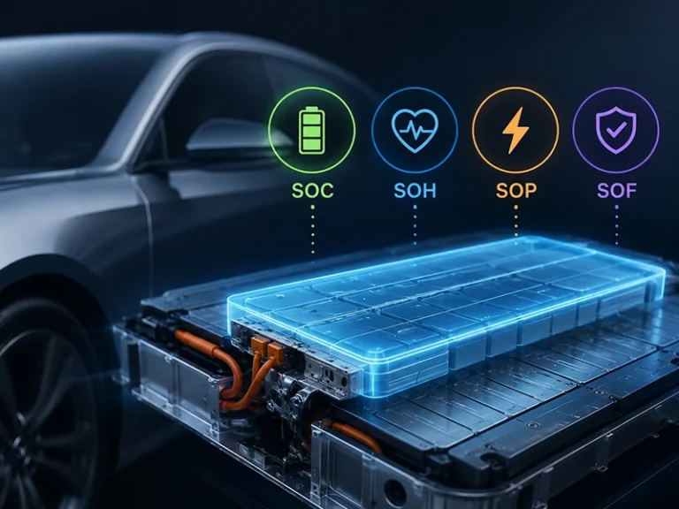
When you validate a battery pack, you need to verify that the Battery Management System (BMS) correctly monitors cell voltage, pack current, temperature, and state conditions under real operating scenarios. A BMS testing system lets you simulate battery signals and electrical conditions without relying solely on physical cells. You can test protection thresholds, balancing functions, SOC/SOH estimation, fault detection, communication interfaces, and control responses in a controlled environment. By reproducing overvoltage, undervoltage, overcurrent, overtemperature, and sensor faults, you can identify BMS logic errors before pack-level deployment. This approach improves validation coverage while reducing test time, battery cycling, and development risk.
What is a Battery Management System (BMS)
A Battery Management System (BMS) is an electronic control system that monitors and controls the electrical and thermal state of a Battery Pack. It is used to measure the cell voltage, pack current, temperature, and State of Charge (SOC) and to control cell charging, discharging, and cell balancing. The BMS will also sense and activate protective measures for abnormal conditions like over-voltage, undervoltage, overcurrent, short circuit and excessive temperature.
For EVs and energy storage systems, the BMS can interact with other controllers to ensure safe operating conditions, maximize battery performance, and minimize battery degradation. When it is validated, its monitoring, protection, balancing, control logic and communication functions should be checked under normal and fault conditions.
How Does a BMS Testing System Work?
The basic workflow is:
Simulation → BMS Under Test → Response Monitoring → Data Acquisition → Analysis → Test Result
A BMS testing system works by simulating real battery conditions and monitoring how the Battery Management System responds. The system first generates controlled inputs such as cell voltage, pack current, temperature, SOC, and fault conditions, which are sent to the BMS under test. The BMS processes these signals and performs functions such as monitoring, cell balancing, protection, contactor control, and communication.
The testing system then captures the BMS outputs and response data through data acquisition and communication interfaces such as CAN or CAN FD. Engineers analyze the recorded measurements, protection responses, and timing against predefined test criteria to identify faults and verify whether the BMS performs correctly under normal and abnormal operating conditions.
BMS Testing Equipment and Tools
| Equipment Category | Primary Testing Purpose |
| Cell Voltage Simulator | Simulates individual cell voltages and verifies BMS measurement and protection functions |
| Temperature Simulator | Reproduces temperature sensor signals and tests thermal protection logic |
| Battery/Pack Simulator | Reproduces dynamic battery operating conditions without using a physical battery pack |
| Programmable Power Supply | Provides controlled voltage and power for BMS power-input testing |
| Electronic Load | Simulates charge/discharge loads and current conditions |
| Current Sensor Simulator | Tests BMS current measurement accuracy and current-related protection |
| Fault Injection Unit | Simulates abnormal conditions such as sensor faults, overvoltage, undervoltage, and communication failures |
| CAN/LIN Interface | Monitors and validates BMS communication and diagnostic messages |
| DAQ System | Collects voltage, current, temperature, timing, and other test data |
| HIL Platform | Runs real-time battery models and evaluates BMS behavior under dynamic operating scenarios |
How to Test a BMS: Step-by-Step Testing Procedure
A structured BMS test procedure confirms that the system is functioning properly under normal operating conditions, boundary conditions and fault scenarios before deployment of the battery pack.
A structured BMS test procedure helps you verify individual functions systematically.
Step 1: Verify BMS Power and Communication
Confirm that the BMS powers up correctly and communicates with the test system. Check CAN messages, diagnostic communication, and required initialization sequences.
Purpose: Ensure the BMS can operate and communicate correctly before functional testing begins.
Step 2: Test Cell Voltage Measurement
Apply known voltage values to individual BMS cell-input channels and compare the reported values with the reference values.
Purpose: Verify cell voltage measurement accuracy and identify channel-level errors.
Step 3: Test Temperature Measurement
Simulate different temperature sensor conditions, including normal, high-temperature, and low-temperature states.
Purpose: Confirm that temperature measurements and thermal protection thresholds operate correctly.
Step 4: Test SOC and SOH Functions
Provide controlled operating conditions or simulated battery data to evaluate SOC and SOH estimation algorithms.
Purpose: Determine whether battery-state calculations remain accurate under different operating conditions.
Step 5: Test Cell Balancing
Create controlled voltage differences between cells and observe whether the BMS activates the appropriate balancing strategy.
Purpose: Verify balancing thresholds, timing, control logic, and balancing behavior.
Step 6: Test Protection Functions
Simulate conditions such as:
- Cell overvoltage
- Cell undervoltage
- Pack overvoltage
- Overcurrent
- Short circuit
- Overtemperature
- Undertemperature
Purpose: Verify that the BMS detects unsafe conditions and activates the appropriate protection response.
Step 7: Test Contactor and Control Outputs
Evaluate pre-charge, main contactor, charging, and other control signals where applicable.
Purpose: Confirm that the BMS executes the correct control sequence during startup, charging, discharging, and fault conditions.
Step 8: Test Communication and Diagnostics
Check CAN/CAN FD or other supported communication interfaces under normal and fault conditions.
Purpose: Verify that the BMS transmits accurate battery information and diagnostic messages to the vehicle or energy-storage controller.
Step 9: Perform Dynamic and HIL Testing
Use a battery model or HIL platform to reproduce changing load, temperature, SOC, and fault conditions.
Purpose: Evaluate BMS behavior under realistic dynamic operating scenarios rather than isolated static conditions.
Step 10: Record and Evaluate Results
Compare measured results against predefined acceptance criteria and generate a complete test report.
Purpose: Provide traceable evidence that the BMS meets functional and performance requirements.
BMS Testing Levels: From Cell to Pack
| Test Level | What You Test | Key Parameters | What It Validates |
| 单元格级别的测试 | Individual cell measurement and protection inputs | Cell voltage, temperature, sensor accuracy, sampling rate | Confirms the BMS receives accurate and timely cell data |
| 模块级测试 | CMC sensing and fault detection | Open-wire faults, channel drift, sensor faults, cell imbalance | Verifies reliable monitoring when individual sensing channels fail |
| 打包级测试 | High-voltage protection and power-path control | Overcurrent, overvoltage, undervoltage, contactors, precharge | Confirms the BMS can isolate and protect the complete battery pack |
| Thermal Testing | Temperature monitoring and thermal protection | Temperature rise, derating, cooling requests, shutdown thresholds | Ensures thermal limits trigger before unsafe conditions develop |
| Cell Balancing Testing | Balancing performance across cells | Cell voltage difference, balancing current, balancing duration, SOC | Verifies that the BMS controls cell-to-cell variation during cycling |
| Communication Testing | BMS and external controller communication | CAN, LIN, SPI, message timing, fault messages | Confirms reliable data exchange between BMC, CMC, and vehicle controllers |
| Fault-Injection Testing | BMS response to abnormal conditions | Sensor faults, communication loss, current spikes, voltage faults | Validates fault detection, protection logic, recovery, and fault latching |
| HIL Testing | Closed-loop BMS software and hardware behavior | Dynamic battery models, SOC/SOH, transient conditions, combined faults | Exposes software and control-logic failures before physical pack testing |
BMS Standards Set Requirements, Not the Full Validation Strategy
Although BMS testing standards provide minimum standards for safety, traceability, and test coverage, they do not mandate all of the requirements for validating a battery pack. Measurable acceptance criteria, controlled fault injection, response-time limits and repeatable test conditions remain a must. Typically, standard checklists will validate specific needs and neglect interactions between several faults.
For EV battery programs, failures can occur due to the interaction of the following factors: sensor drift, SOC estimation error, thermal conditions, and contactor timing. A comprehensive validation plan thus connects measures at the cell level, responses to protection, heat response, balancing, communication and closed-loop software validation. Assume that the standards are the lowest level of compliance, and then test the full BMS under realistic operating and fault conditions.
BMS Testing System vs. Conventional Battery Testing
A BMS testing system focuses on validating the BMS itself, while conventional battery testing primarily evaluates the electrical and performance characteristics of the battery. The two approaches can complement each other, but they serve different validation objectives.
| Parameter | BMS Testing System | Conventional Battery Testing |
| Primary purpose | Validate BMS monitoring, protection, control, and communication functions | Evaluate battery capacity, power, energy, efficiency, and cycle life |
| Test inputs | Simulated cell voltage, current, temperature, SOC, and fault signals | Actual battery cells, modules, or complete packs |
| Fault simulation | Supports controlled overvoltage, undervoltage, overcurrent, sensor, and communication faults | Fault simulation is generally limited and may require physical battery conditions |
| BMS communication | Tests CAN, LIN, SPI, and BMS-to-controller communication | Usually focuses on battery electrical behavior and test-system communication |
| Cell balancing | Can emulate cell-to-cell voltage/SOC differences to verify balancing logic | Measures balancing behavior mainly on physical cells |
| HIL capability | Supports Hardware-in-the-Loop testing with real-time battery models | Usually not designed primarily for BMS software validation |
| Test repeatability | High; identical cell and fault conditions can be reproduced digitally | Lower when physical cell variation affects results |
| Safety during fault testing | Faults can often be simulated without deliberately damaging a battery | Physical fault testing can involve higher electrical and thermal risks |
| 典型应用 | BMS development, validation, fault injection, HIL, production testing | Battery characterization, performance testing, aging, and cycle-life evaluation |
How to Choose a BMS Testing System
Before selecting a BMS testing platform, evaluate the following technical requirements.
Voltage and Current Range
Choose a system that supports the maximum cell and pack voltage ranges required for your application. Leave sufficient headroom for future battery designs.
Number of Channels
Consider how many cell voltage and temperature channels you need to simulate simultaneously. A modular system is preferable if your battery configurations vary.
Battery Simulation Capability
The system should reproduce realistic battery conditions rather than only fixed voltage signals. Dynamic simulation becomes particularly important for advanced BMS development.
Fault Injection
Check whether the platform can deliberately reproduce relevant electrical, sensor, thermal, and communication faults with controlled timing and conditions.
Communication Interfaces
Verify support for the communication protocols used by your BMS, such as CAN, CAN FD, LIN, or other required interfaces.
Hardware-in-the-Loop Capability
For advanced R&D, HIL capability allows you to connect the actual BMS to a real-time battery model and evaluate its response to dynamic operating scenarios.
Data Acquisition and Analysis
Look for accurate, synchronized data acquisition with sufficient sampling speed and automated pass/fail analysis. This is important when protection response depends on timing.
Automation and Software
Automated test sequencing can reduce manual work and improve repeatability. Consider scripting, test-case management, data logging, reporting, and integration with existing laboratory software.
可扩展性
Your testing requirements may grow from cell-level BMS development to module, pack, and production testing. A modular architecture can help you expand channel count and functionality without replacing the entire system.
结论
A proper BMS should be capable of measuring the cell voltage and the temperature. The verifications required are: Measurement accuracy, Protection timing, Cell balancing, Thermal response, Communication, Fault recovery under repeatable operating conditions. Using a BMS testing system, you can simulate single cells, pack conditions, and abnormal situations to observe the controller’s reactions. HIL testing can even uncover software and control-logic problems prior to physical pack validation. Cell-level checks and pack protection, along with thermal and communication testing and closed-loop testing, can detect failures earlier and minimize the risk of validation.
Looking for a scalable BMS testing solution? Contact us to discuss your required voltage range, channel count, test scenarios, and battery-pack validation objectives.
常见问题
Why is BMS testing important for battery pack validation?
It helps you identify sensing errors, protection failures, balancing issues, communication faults, and software problems before deploying the BMS in a physical battery pack.
What can a BMS testing system test?
You can test cell voltage, current, temperature, SOC, cell balancing, overvoltage, undervoltage, overcurrent, thermal protection, contactors, communication, and fault recovery.
Can a BMS testing system simulate individual battery cells?
Yes. It can independently simulate cell voltage and operating conditions, allowing you to reproduce cell imbalance, abnormal voltage, and other cell-level faults.
Can BMS testing include CAN, LIN, and SPI communication?
Yes. Depending on the system configuration, you can test communication between the BMS, CMC, BMC, vehicle controller, and other electronic control units.
How does BMS testing improve battery safety?
It verifies whether the BMS detects abnormal conditions and responds within defined limits by reducing current, disconnecting the pack, triggering thermal protection, or entering a safe state.